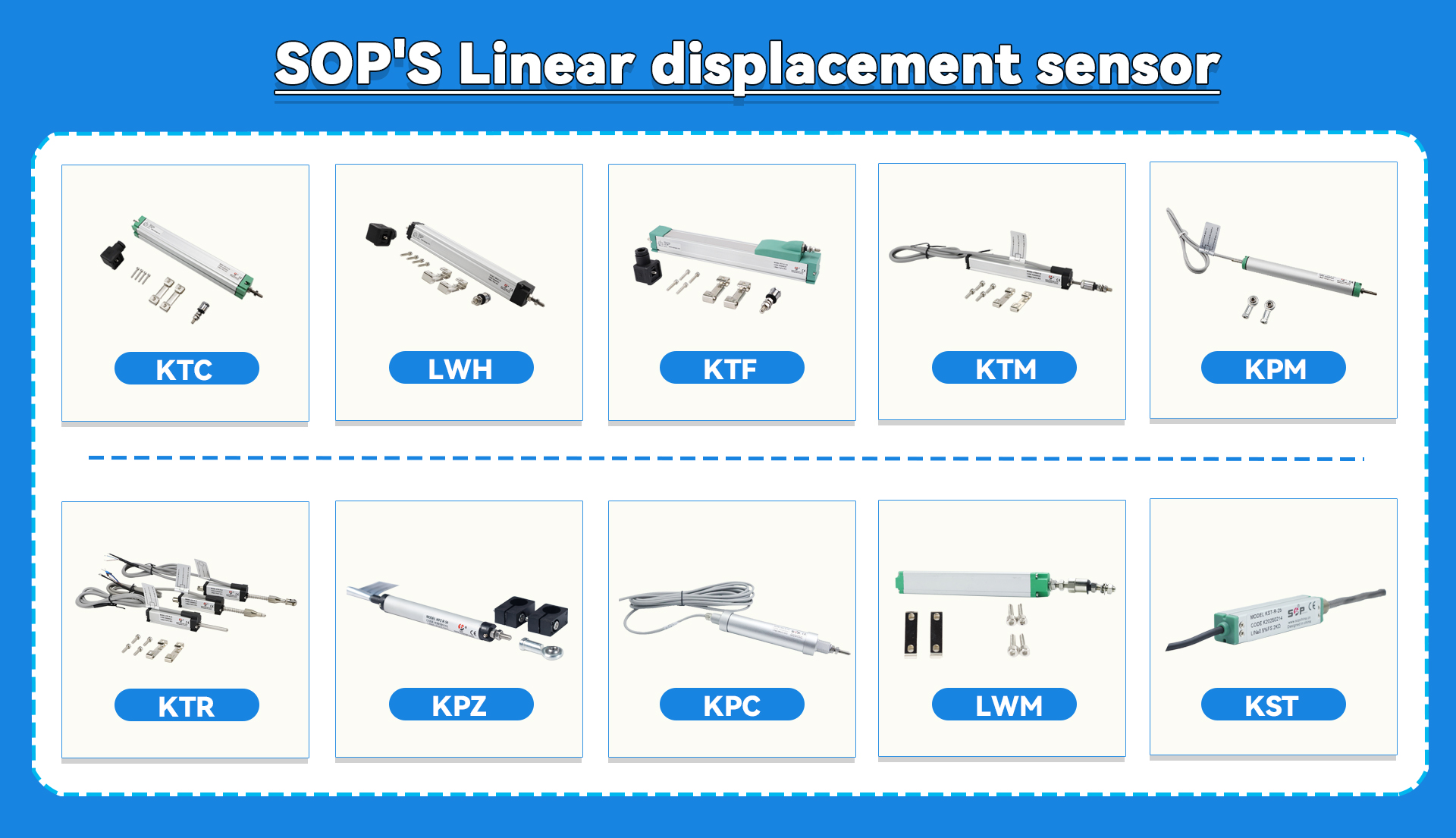
Installation and debugging of linear displacement sensor
Installation and debugging of linear displacement sensor
Installing and debugging linear displacement sensor is a key step to ensure accurate measurement of equipment. The following is the detailed installation and debugging process:
一、 the installation of linear displacement sensor
1. Determine the installation location: Determine the installation position of the sensor according to the specific requirements of the equipment. Ensure that the installation position can fully meet the requirements of measuring range and accuracy. Considering the sensor's alignment, the measurement data is not accurate due to improper installation position.
2. Prepare to install the bracket: Prepare a suitable mounting bracket to ensure that the bracket can support the sensor stably and allow the sensor to move smoothly with the measured object. Install the bracket in the predetermined position, and reserve appropriate adjustment space.
3. Fixed sensor: Fix the sensor to the bracket, and usually use screws to connect the sensor to the bracket. When fixing, the contact between the sensor and the measured object should be ensured to be good. For the pull-rod displacement sensor, pay attention to the centering of the ball universal joint, and allow the centering deviation with a radius of 1 mm. The shorter the specification, the smaller the recommended centering deviation. Ensure that the sensor is firmly installed to avoid displacement due to vibration during measurement.
4. Electrical connection: Connect the power line and signal line according to the wiring diagram of the sensor. Ensure that all connections are firm and correct to prevent poor electrical contact. Use four-wire system or wiring with shielded wire to ensure that the shielding layer of signal wire is reliably grounded at the end of electric cabinet to reduce electrostatic interference.
5. Adjustment and installation: After the sensor is installed, adjust the gap between the sensor and the measured object to ensure that the sensor can work normally within the measuring range. If there is a big misalignment when the pull rod is pulled out, the mounting bracket near the plug should be adjusted. Ensure that when the pull rod is retracted, the cylindrical body of the universal ball head can have gaps in four radial directions, otherwise the installation position needs to be adjusted.
6.Precautions: Ensure that the sensor has good dustproof and waterproof ability, and avoid dust and moisture from affecting the internal circuit of the sensor. Do not exceed the maximum displacement range allowed by the sensor to avoid damaging the sensor. Regularly clean the dust and dirt on the sensor surface, and check whether the wires and connectors are reliable.

二、 the linear displacement sensor debugging
1. Connect the power supply and signal line: Connect the power cord of the displacement sensor to an appropriate power supply to ensure that the sensor can work normally. Connect the signal line of the sensor to the corresponding control system or data acquisition equipment.
2. Zero calibration: Place the measured object in the zero position, and perform zero calibration according to the model and requirements of the sensor. Normally, it is adjusted by rotating or moving the zero calibration screw.
3. Linearity calibration: Move the measured object in the whole measuring range of the sensor, record the output values of the sensor at different positions, and compare them with the actual displacement. If there is linearity deviation, it can be calibrated by adjusting the linearity calibration parameters of the sensor.
4. Sensitivity calibration: According to the actual application, the sensitivity setting of the sensor is adjusted to meet different measurement requirements. Sensitivity calibration can adjust the amplitude of output signal and ensure the accuracy of measurement results.
5. Data collection and testing: Connect the sensor to the corresponding control system or data acquisition equipment, and collect and test the data. Use relevant software or tools to analyze and process the measurement data and verify whether the measurement results of the sensor meet the requirements.
6. Verification and adjustment: Verify the consistency between the measured results of the displacement sensor and the actual displacement. Make fine adjustments as needed until the measurement requirements are met.
7. Data collection and testing: Connect the sensor to the corresponding control system or data acquisition equipment, and collect and test the data. Use relevant software or tools to analyze and process the measurement data and verify whether the measurement results of the sensor meet the requirements.
8. Verification and adjustment: Verify the consistency between the measured results of the displacement sensor and the actual displacement. Make fine adjustments as needed until the measurement requirements are met.
Through the above steps, the correct installation and debugging of the linear displacement sensor can be ensured, thus playing an accurate and stable role in practical application.

